
Integrating SD-WAN with AWS for High-Performance Networking Part 1
23 February 2024
In today’s fast-paced digital landscape, where cloud computing has become the backbone of modern business operations, achieving fast and reliable cloud connectivity is paramount. Organizations are increasingly adopting cloud services to leverage the scalability, flexibility, and cost-efficiency they offer and to drive innovation and streamline operations.
SD-WAN and Cloud Connectivity
However, traditional networking approaches often struggle to keep up with the demands of the cloud, leading to performance bottlenecks, latency issues, and limited scalability. Additionally, organizations strive for uninterrupted connectivity to the cloud, enabling effortless access to cloud-based applications and resources.
This connectivity fosters improved collaboration and productivity among geographically dispersed teams. Enter SD-WAN (Software-Defined Wide Area Network): SD-WAN uses software-based controls to manage and optimise wide area networks. It has long been used to establish connections over the internet between branch offices and data centres. It replaces expensive and proprietary hardware devices with software-defined networking principles, offering flexibility, scalability, and cost efficiency.
SD-WAN allows for centralised management, dynamic resource allocation, automated traffic routing, and application-based policies. It can utilise multiple network connections simultaneously, improving performance, reliability, and cost optimisation. It also integrates with security systems for enhanced protection and is popular for its agility, cost savings, and network performance improvements.
Amidst the current backdrop, it has become necessary for networks to expand and connect to cloud services. Inasmuch as SD-WAN excels in optimizing and managing network traffic between locations, it is not specifically optimized for connecting to cloud environments. Cloud environments often rely on different networking technologies, such as virtual private clouds (VPCs) or direct cloud connectivity. These technologies require specific configurations and integration points that may not be supported by traditional SD-WAN solutions out of the box.
Evolution of SD-WAN Solutions for Cloud Connectivity
As a result, adapting traditional SD-WAN infrastructure to connect to cloud services can introduce complexity, requiring additional configurations, integrations, and potential customizations. To address these challenges, newer generations of SD-WAN solutions have emerged that are specifically designed to support cloud connectivity.
These solutions often provide native integrations with major cloud platforms, advanced security features, and enhanced automation capabilities to simplify the management and optimization of network connections to the cloud. In this blog, we will discuss a specific integration between SD-WAN and AWS Cloud that utilizes Transit Gateways and a third-party appliance. For the third-party appliance, we are going to consider the Fortinet Fortigate as a case in point.
Transit Gateway (TGW) simplifies network connectivity between multiple virtual private clouds (VPCs) and on-premises networks by acting as a hub that enables centralized management and routing of network traffic. This simplifies network architecture and reduces the need for complex peering relationships between VPCs.
It also enables network segmentation by using separate route tables for different VPCs or on-premises connections which provides improved security and isolation between different network environments. Previously, extending SD-WAN into AWS involved establishing IPsec VPNs between the SD-WAN network virtual appliances deployed on AWS and TGW or solely relying on VPC attachments. Even though these architectural patterns are feasible, they are not without drawbacks such as limited bandwidth, increased operation burden, etc.
To address these challenges and minimize the limitations of the aforementioned architectural approaches, AWS introduced TGW Connect. TGW Connect is an attachment that leverages an existing VPC or Direct Connect attachment to establish a connection between a Transit Gateway (TGW) and a third-party virtual appliance. It utilizes the underlying transport mechanism provided by the VPC or Direct Connect attachment. TGW Connect attachment supports Generic Routing Encapsulation (GRE), delivering enhanced bandwidth performance of 20 Gbps, surpassing the 1.25 Gbps typically achieved with a Site-to-Site VPN connection.
Moreover, incorporating Border Gateway Protocol (BGP) for dynamic routing eliminates the requirement for manual configuration of static routes or custom automation. This streamlined approach simplifies network design, leading to more efficient operations and reduced associated costs. We’ve done quite a bit of reading. Let’s delve into the architecture, shall we?
Architecture overview

Figure 1: Network Architecture
The diagram above has a Virtual Fortigate running in an availability zone (AZ). It has an Edge VPC which facilitates direct, secure, and accelerated connectivity between edge locations and AWS services. An edge location typically represents a remote site or branch office that requires direct access to AWS services and resources.
The virtual Fortigate running on an EC2 instance has two ports — Port 1 has a public IP for internet connectivity and Port 2 for establishing a Connect Attachment between the Fortigate and the TGW. GRE tunnels or Transit Gateway Connect Peers in AWS lingua connect the TGW and the virtual Fortigate. A GRE tunnel is a network protocol that encapsulates a protocol’s data packet within another protocol (i.e. wraps one data packet within another data packet) for direct point-to-point connection across a network. It encapsulates the original IP payload with a new IP header.
Two TGW Connect Peers or BGP peering sessions are established between the virtual Fortigate and the TGW to ensure redundancy in the routing plane and exchange of routing information. This configuration enhances reliability and fault tolerance by providing redundant paths for routing information exchange.
Additionally, the two BGP peering sessions serve as a safeguard against any AWS infrastructure operations, including routine maintenance, patching, hardware upgrades, and replacements. This redundancy ensures continuous availability and minimizes disruptions during such operational activities. The TGW Connect attachment is associated with the Ingress Route Table hence the TGW will advertise the routes within the Ingress Route table to the virtual Fortigate. Routes advertised from the virtual Fortigate can be propagated to the Ingress or Egress Route table via the Connect attachment.
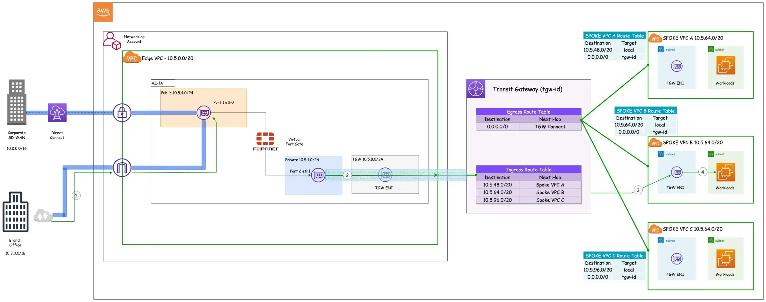
Figure 2: Traffic Flow - Ingress
- Traffic originating from the branch and headed for spoke VPC B follows the path of the SD-WAN overlay, traversing the internet and reaching the internet gateway of the Edge VPC. From the internet gateway, it’s routed to Port 1 of the virtual Fortigate.
- From the virtual Fortigate, the traffic is forwarded to the TGW via the connect attachment.
- Based on the destination IP address, the TGW ingress route table determines the VPC attachment to be used. In this scenario, as the traffic is intended for workloads in Spoke VPC B, the TGW ingress route table selects the Spoke VPC B attachment.
- The traffic is forwarded to the destination by the Transit Gateway Elastic Network Interface (ENI) of Spoke VPC B.
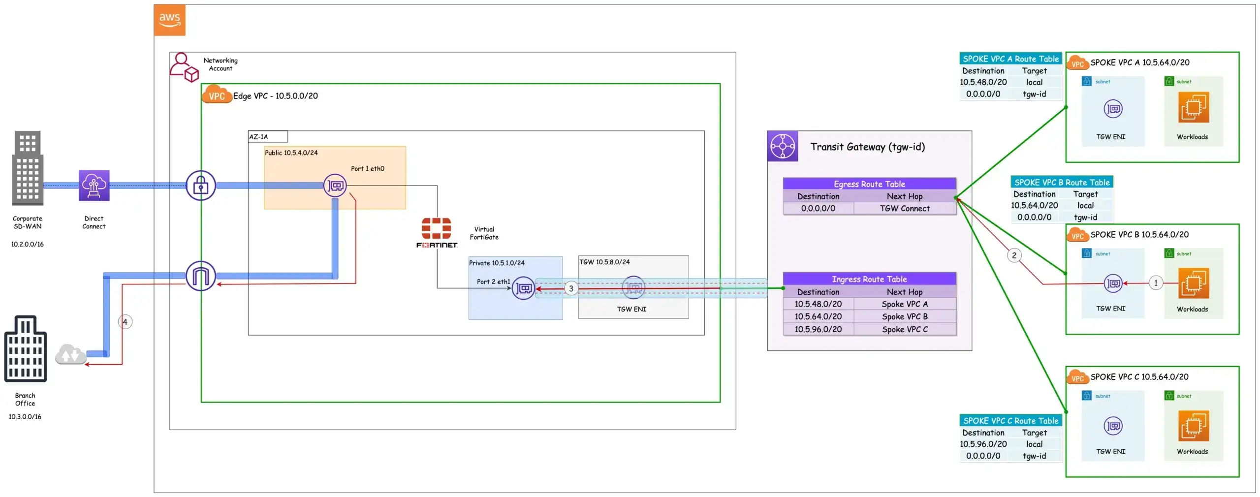
Figure 3: Traffic Flow - Egress
- Traffic from workloads in Spoke VPC B destined for the Branch Office [10.3.0.0/16] is routed to the TGW ENI.
- The traffic is then forwarded to the TGW. All the Spoke VPCs have an attachment to the Egress Route Table.
- The TGW Egress route table uses the TGW Connect attachment to forward all traffic to the Virtual Fortigate.
- The Virtual Fortigate uses the SD-WAN overlay to reach the Branch Office.
Dynamic Routes
We have exclusively addressed static routes within the TGW route table. However, let’s explore the role of dynamic routing within this architecture and gain an understanding of its significance. What exactly are dynamic routing protocols and how do they integrate into this framework? Dynamic routes are automatically learned and updated by network devices through the use of routing protocols like BGP.
In contrast to static routes, which necessitate manual configuration by network administrators, dynamic routes are exchanged and adjusted automatically in response to network conditions and modifications. As a result, dynamic routes remain current and can adapt to network changes, while static routes may become obsolete and result in routing errors. They provide benefits such as simplified network management, reduced manual configuration, improved network scalability and flexibility, etc.
To propagate dynamic routes to the route tables of the TGW, the Fortigate has to be configured to advertise learned routes to the TGW. By leveraging the established GRE Tunnel between the Transit Gateway (TGW) and Fortigate, the Fortigate appliance utilizes BGP to propagate and advertise routes to the TGW route tables.
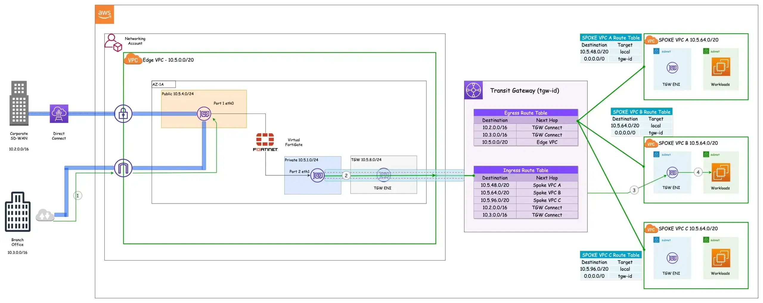
Figure 4: Dynamic Routes
The TGW Route table now has dynamic routes which are the prefixes of the branch office and the corporate SD-WAN. The next hop for the dynamic routes are the TGW Connect attachments while the next hop for the Spoke VPCs are the VPC attachments. Even though the TGW has four VPC attachments and a connect attachment, they are not equally visible in both route tables.
Why is that? TGW has the concept of route table association and route propagation. When a TGW route table is associated with an attachment, the routes within the route table are propagated to the attachment. In other words, that association determines which route table is used to control traffic routing for that attachment. In the diagram above, the Spoke VPCs are associated with the Egress Route Table hence the only destination reachable from the Spoke VPCs are those indicated in the Egress Route Table. Route Propagation, on the other hand, shares attachment routes with route tables.
Let’s take this apart. Each attachment is accompanied by one or more routes. The Spoke VPCs have a route which is the CIDR of the respective VPCs. These routes can be propagated to any Route Table of choice within the TGW. The architecture above reveals an interesting observation. Despite the VPC attachments of the Spokes being associated with the Egress Route Table, their routes, however, can be propagated to the Ingress Route Table.
This configuration enables Spoke VPC isolation, which proves valuable when implementing network segmentation. In the same vein, the Edge VPC and Connect attachments are associated with the Ingress Route Table, and their routes are propagated to the Ingress and Egress Route Tables.
Considerations for implementation
The TGW can support a maximum of 1000 dynamic routes advertised from a virtual appliance to the TGW Route Tables via the Connect Attachments as of this writing. This is a hard limit that cannot be adjusted, at least for now.
In large networks where more than 1000 dynamic routes are required or involved, route aggregation or summarization can be used to reduce the number of individual routes advertised from the virtual appliance to the TGW route table. Route aggregation combines multiple smaller network prefixes or subnets into a single large prefix. Additionally, route aggregation improves routing efficiency and improved network performance.
Another consideration is the bandwidth capabilities of the VPC attachments and Connect attachments. Each TGW connect peer supports a maximum of 5 Gbps as opposed to 50 Gbps supported by a VPC attachment. The maximum supported bandwidth of the connect attachment can be adjusted by creating 4 connect peers (GRE Tunnels) per transit gateway connect attachment and using ECMP (Equal-Cost Multipath) to load balance traffic across the connect peers.
Lastly, the network topology discussed above focused on a single AZ virtual appliance topology. This is not ideal, we wouldn’t want an entire organization’s SD-WAN extension to the cloud to be reliant on a single AZ single virtual appliance topology with multiple single points of failure. Addressing this, however, poses some interesting challenges which will be discussed in the second part of this blog so stay tuned.
Conclusion
The first part of this blog post delved into SD-WANs and their integration with cloud environments. We explored how to use the AWS TGW connect attachment and Fortinet Fortigate to advertise prefixes/routes to the TGW route tables with BGP thereby extending SD-WAN into AWS with a higher bandwidth as compared to IPsec VPNs and reducing the complexity associated with managing static routes. In the second part of this post, we will explore the concept of High Availability (HA) architecture, addressing the associated implementation challenges and proposing mitigation strategies.


Get in Touch.
Let’s discuss how we can help with your cloud journey. Our experts are standing by to talk about your migration, modernisation, development and skills challenges.
